Perspectives of high temperature electrolysis using
SOEC
S. H.
Jensen and
M. Mogensen
Materials Research
Department, Risø National Laboratory, DK-4000
1. Abstract
Inefficient
conversion technologies as well as improper energy storage systems are major
barriers for a wider application of renewable energy such as wind, photovoltaic
and hydropower. Reversible Solid Oxide Cells (SOC) that can be used both as
Solid Oxide Fuel Cells (SOFC) and as Solid Oxide Electrolyser Cells (SOEC),
have the potential to become a cost effective way to solve the conversion
problem: SOEC can split H2O into H2 and O2.
When need is H2 can be utilized in SOFC with high efficiency.
SOEC has also the potential of splitting carbon
dioxide into carbon monoxide and oxygen. This means that electrolysis of a
mixture of steam and carbon dioxide results in a mixture of hydrogen and carbon
monoxide (syngas). A number of other carbon energy carriers may be produced
from syngas. The two simplest are methanol and methane, but also gasoline may
be produced. Here the production of H2 and CH4 using high
temperature electrolysis of steam and CO2 are investigated. For an
optimized system, assuming an electricity price of 3.6 US$/GJ, H2
production price will be 4.8
2. Introduction
Renewable
energy has received increasingly interest over the last decades. If renewable
energy is to be implemented in the energy infra structure high delivery
stability is demanded. SOEC can produce chemical energy carriers that are easy
to store such as H2, CH4 or CH3OH when energy
from renewable energy sources is available.[1]
When society needs energy and no renewable energy source is available, the
chemical energy carrier can be utilized in SOFC to produce electricity.
A
system consisting of a heat exchanger and a reversible SOC has a lot of
advantages compared to other conversion techniques. Here is listed a few for
the SOEC part:
Because
water electrolysis is increasingly endothermic with temperature, electricity
demand can be significantly reduced, if the formation of hydrogen is taking
place at high temperatures (600-1000 °C). The electric energy need is reduced because the
unavoidable joule heat of an electrolysis cell is utilized in the water (steam)
splitting process at high temperature.
If
heat is available from sources such as heat of geothermal (e.g. on
SOEC can
split carbon dioxide into carbon monoxide and oxygen. This means that
electrolysis of a mixture of steam and carbon dioxide results in a mixture of
hydrogen and carbon monoxide called syngas. By catalytic reactions a number of
other energy carriers may be produced from syngas. The two simplest are
methanol and methane. The latter is the main constituent in natural gas.
The
preferred catalyst for CH4 formation is Ni. Since the negative
electrode of a SOC is partly made of Ni it is possible to produce CH4
within the cell.[2] The entropy change for CH4
production from CO2 and H2O is nearly zero. This means
that the overall efficiency for a conversion of electricity to CH4
and back again can be very high if the reaction kinetics is high, since only
small reaction entropy losses occur.
The
catalytic reaction to form CH4 or CH3OH from syngas can
also be done in the heat exchanger after the cell. (See system description in Figure 4) This means that the energy for H2O
vaporization can be produced within the system. A combination of the two ways
to produce CH4 may prove to be the best production method, since it
seems to optimize efficiency and production speed.
Also, the
energy losses due to the sluggishness of the electrochemical reactions are in
principle the lower, the higher the temperature is. This principle seems to a
large degree realised in practise through the significant improvements of the
SOFC technology due to the extensive international development efforts. Thus,
SOEC is probably more efficient than the already commercialised low temperature
electrolysers, and today’s SOFC should be tested in the SOEC mode in order to
assess the commercial potential of the technology in this application.
3. Theoretical background
The
principle of SOC is shown in Figure
1. The cell basically consists of
three different layers. The middle layer (white) is an oxide ion-conducting
electrolyte that is gastight. The topmost layer is the positive electrode and the
down most is the negative electrode. The electrodes are porous, electron and
oxide ion conducting in order to get the gasses into the reaction sites and to
get a high three phase boundary where the three species (gas molecules, oxide
ions and electrons) can meet and react. A cell voltage is established over the
electrodes when gasses with different oxygen partial pressures are fed to the
electrodes as described by Nernst equation.[3] The left figure shows SOC in fuel
cell mode, where H2 is fed to the cell and reacts with oxide ions to
form H2O. If the electrodes are connected through an external
circuit with a light bulb, electrons will flow from the down most electrode to
the topmost electrode through the circuit as long as gas is fed to the
electrodes. In electrolysis mode the reaction is the reverse as in fuel cell
mode. Here the electrons are forced to the negative electrode by an external
voltage supply (indicated as a wind mill) where H2O is split and H2
and O2 is formed.

Figure 1: The principle of a Solid Oxide Cell (SOC). The cell basically consists
of three different layers. The middle layer (white) is an ion-conducting
electrolyte that is gastight. The topmost layer is the positive electrode and
the down most is the negative electrode. The left figure shows SOC in fuel cell
mode, where H2 is fed to the cell and reacts with oxide ions to form
H2O. The reaction continues as long as electrons are allowed to pass
through the light bulb in the external circuit and gasses are fed to the
electrodes. The right figure shows SOC in electrolysis mode where the reaction
is the reverse as in fuel cell mode. Here electrons are forced to the negative
electrode by an external voltage supply, indicated as a windmill. This forces
oxide ions (taken from H2O) to migrate through the electrolyte from
the negative down most electrode to the topmost.
The
overall reaction of the water electrolysis is:
The reaction at the negative electrode is:
![]()
and at the positive electrode:
![]()
The
minimum electric energy supply necessary for the electrolysis process is equal
to the change in free energy (Gibbs free energy)
where DH
is the enthalpy change, T is the temperature in Kelvin and DS
is the entropy change by the reaction. The total energy
necessary for the electrolysis reaction is DH.
TDS
is the heat necessary for the reaction to take place. The relation between DG
and the equilibrium potential (no current through the external circuit) for the
cell is
where n
is the number of electrons involved in the reaction, F
is faradays constant and ![]() is the equilibrium
voltage, which sometimes is called the electromotive force. The value of
is the equilibrium
voltage, which sometimes is called the electromotive force. The value of ![]() is dependent on the
actual partial pressures of the reactants and products as described by the
Nernst equation:
is dependent on the
actual partial pressures of the reactants and products as described by the
Nernst equation:
where ![]() is at standard pressure, (
is at standard pressure, (![]() ) R is the ideal gas constant,
) R is the ideal gas constant, ![]() is the oxygen partial pressure at the positive electrode,
is the oxygen partial pressure at the positive electrode, ![]() are the partial pressures of H2 and H2O
respectively at the negative electrode.
are the partial pressures of H2 and H2O
respectively at the negative electrode.
If
equation is
inserted in we get
Since
both ![]() and
and ![]() are positive for the
reaction in equation and
approximately independent of T it is seen that
are positive for the
reaction in equation and
approximately independent of T it is seen that ![]() is decreasing with
increasing temperature.
is decreasing with
increasing temperature.
Hydrogen
is formed at the negative electrode whenever a potential difference, V,
larger than ![]() is applied to the
electrodes of the cell, and steam supply is sustained to the negative
electrode. The electric energy demand, given in units of kWh/Nm3 is
illustrated in Fig. 1. The electrical power is determined as -IV,
since the current, I, is taken to be negative in
electrolysis mode and positive in fuel cell mode.
is applied to the
electrodes of the cell, and steam supply is sustained to the negative
electrode. The electric energy demand, given in units of kWh/Nm3 is
illustrated in Fig. 1. The electrical power is determined as -IV,
since the current, I, is taken to be negative in
electrolysis mode and positive in fuel cell mode.
The
passage of current will generate heat inside the cell due to the internal cell
resistance in an amount equal to (![]() -V)I.
If a voltage equal to DH/nF is applied to the electrodes, the joule heat
deposited pr. unit time in the cell is
-V)I.
If a voltage equal to DH/nF is applied to the electrodes, the joule heat
deposited pr. unit time in the cell is
![]()
This is
exactly the heat removal pr. unit time by the steam electrolysis process. For
this reason DH/nF
is called thermo neutral voltage Etn.
Considerable Joule heat is unavoidable when
electrolysis is done at a practical timescale with overall economy optimised.
For this reason SOEC is an interesting technology since the produced joule heat
can be utilized in the highly endothermic electrolysis proces.
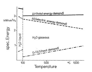
Figure 2:
Thermodynamics of H2O electrolysis, after ref. [4].
The
internal area specific resistance (ASR) for SOEC
decreases rapidly with temperature following an Arrhenius expression.[5]
Furthermore we have
where i is
the current density. Since both ASR and DG
(and thus ![]() ) decrease with temperature, i
increase significantly with temperature when the cell
voltage is kept at Etn. Since the area specific H2
production rate is proportional to i it can be
imagined that increasing the cell temperature will decrease the H2
production price.
) decrease with temperature, i
increase significantly with temperature when the cell
voltage is kept at Etn. Since the area specific H2
production rate is proportional to i it can be
imagined that increasing the cell temperature will decrease the H2
production price.
The optimal cell voltage is, in case only electrical
energy is supplied (no external heat source), close to Etn;
if the cell voltage is increased above Etn
excess heat is produced. Due to heat losses to the
surroundings and in the heat exchanger, nFV
has to be slightly higher than DH.
![]() for the reaction in equation . This is
the necessary cell voltage if no external heat source is available and the
inlet gas is heated in an ideal heat exchanger (see next section). If a heat
source at temperatures above the boiling point of water (100 °C)
or steam is available the energy needed for H2O evaporation is not
necessary and the operating voltage can be decreased to ca.
for the reaction in equation . This is
the necessary cell voltage if no external heat source is available and the
inlet gas is heated in an ideal heat exchanger (see next section). If a heat
source at temperatures above the boiling point of water (100 °C)
or steam is available the energy needed for H2O evaporation is not
necessary and the operating voltage can be decreased to ca.
where ![]() is the evaporation enthalpy of H2O at 0.1 Mpa. The
detailed economical optimisation of cell voltage must take into account the
thermal loss from the electrolyser to the surroundings, degradation speed of
the cell as a function of cell over-voltage (
is the evaporation enthalpy of H2O at 0.1 Mpa. The
detailed economical optimisation of cell voltage must take into account the
thermal loss from the electrolyser to the surroundings, degradation speed of
the cell as a function of cell over-voltage (![]() -V) and production speed cf. eq. . In fact
the real important parameters for the production price are the investment cost
and the cost of electricity as shown in the next section.
-V) and production speed cf. eq. . In fact
the real important parameters for the production price are the investment cost
and the cost of electricity as shown in the next section.
The overall reaction for CO2 electrolysis
is
and ![]() for this reaction. Thus the necessary cell voltage for syngas
production is ca. 1.48 V if no external heat source is available. Like reaction
reaction is very
endothermic which means that if heat can be supplied at the negative electrode
the cell voltage can be reduced significantly.
for this reaction. Thus the necessary cell voltage for syngas
production is ca. 1.48 V if no external heat source is available. Like reaction
reaction is very
endothermic which means that if heat can be supplied at the negative electrode
the cell voltage can be reduced significantly.
At temperatures below about 700 °C syngas may react to form methane, CH4.
The catalytic process is
This process is extremely exothermic which means it
produces a lot of heat. If the reaction is taking place at the negative
electrode the produced heat can be utilized to lower the cell voltage. Reaction
requires
an appropriate catalyst. Dispersed metallic nickel is the catalyst of
preference for this. Fortunately, the SOEC negative electrode is usually made
of a composite of Ni and YSZ (yttria stabilised zirconia), a Ni-YSZ-cermet, and
thus, it is possible to form CH4 directly in the SOEC by
electrolysis of steam and CO2 mixtures.2
This means
that the overall reaction in the SOEC will be
The
minimum cell voltage required for reaction is given
as
where n = 8. Note
that heat for steam rising is included in equation . ![]() for eq. , where
for eq. , where ![]() is the change in free energy for reaction at 1000 K
(where H2O is steam) and where the reactants and products are at
0.1Mpa. Thus the cell voltage found in equation may not
be the economically optimized cell voltage cf. equation and
discussion below eq. .
is the change in free energy for reaction at 1000 K
(where H2O is steam) and where the reactants and products are at
0.1Mpa. Thus the cell voltage found in equation may not
be the economically optimized cell voltage cf. equation and
discussion below eq. .
The possible concentration of methane that can be
obtained without producing equilibrium carbon is decreasing with increasing
temperature, increasing with pressure, and decreasing with steam to carbon
ratio.[6],[7]
If carbon is formed at the three-phase boundary it will slow down the kinetics
of the electrodes.
At 650 °C,
0.1 Mpa, app. 17% methane and 83% H2 (dry gas) can be produced at a
negative electrode potential, V = -1.28 V vs. air without producing
equilibrium carbon. At 15 Mpa and 650 °C,
a mixture of 85% methane and 15% hydrogen dry gas with small concentrations of
CO and CO2 can be produced without producing equilibrium carbon, at V
= -1.08 V vs. air. It is believed that methane could be produced in SOEC at
these pressures, with acceptable costs. The 15 Mpa is taken as an example in
analogy to the production of ammonium, which is normally synthesised at
pressures around 15 Mpa.[8]
4. System description
In order to estimate the production price for H2
production the system sketched in Figure
3 is analysed. A heat exchanger is used in order to
save expenses for heating the feed gas to working temperature of the SOC.
Reversed Osmosis Water is fed through the heat exchanger to the cell. Here it
is split into H2 and O2 where O2 has migrated
trough the gastight electrolyte. On the
way out, H2 and O2 is giving off the heat to the H2O
in the heat exchanger. The detailed economic assumptions and results of the
calculation are given in the next section.
The system analysed for CH4 production is
sketched in Figure
4. Here CO2 and H2O are fed
through the heat exchanger to the cell. At the cell it is split into syngas and
O2. At 0.1 Mpa and 650 oC only small amounts of CO and H2
is catalysed into H2O and CH4 at the electrode. If the
pressure is increased the CH4 concentration can be increased
significantly. If all the catalytic reaction is taking place at the cell the
steam formation from reaction can be
split into H2 and O2 and the H2 can then be
used in reaction . This
gives a very low steam to carbon ratio, where nearly all the steam is utilized,
and thus a high CH4 concentration. The low steam to carbon ratio
could give problem with carbon formation at the electrodes, but this can be
avoided by increasing the pressure.
Figure 3: System for H2 production by electrolysis of steam. The
drawing is not to scale. Reversed Osmosis Water is fed through the heat
exchanger to the cell. Here it is split into H2 and O2
where 2O-2 migrates trough the gastight electrolyte and O2
is formed at the positive electrode as long as steam is fed to the negative
electrode and ![]() . On the way out, H2
and O2 is giving off the heat to the H2O in the heat
exchanger. The normal working temperature for SOC is between 600 oC
and 1000 oC.
. On the way out, H2
and O2 is giving off the heat to the H2O in the heat
exchanger. The normal working temperature for SOC is between 600 oC
and 1000 oC.
Figure 4: System for production of CH4 by electrolysis of steam and
CO2. CO2 and H2O are fed through the heat
exchanger to the cell. Here it is split into H2 and CO and O2. At 0.1 Mpa and 650 oC only small
amounts of CO and H2 is catalysed into H2O and CH4
at the negative electrode. Therefore a Ni catalyst is placed downstream in the
heat exchanger, where the temperature is lower. If the pressure is increased,
more CH4 can be produced at the negative electrode. The exothermic
formation of CH4 from syngas produces heat that can be utilised
within the system. If the heat is
produced at the negative electrode, the heat can be used to reduce the cell
voltage. If the heat is produced downstream at the catalyst the heat can be
used for steam rising.
Another way to increase the CH4-concentration
in the outlet gas is to use a catalyst of dispersed metallic nickel placed down
stream in the heat exchanger, where the temperature is lower. Using this
technique the steam to carbon ratio will be higher, but this also means that
the problems of avoiding carbon formation at the electrodes would be smaller.
If no CH4 is formed at the negative electrode, the necessary cell
voltage will be between 1.29 V and 1.47 V depending on the ratio between CO2
and H2O in the inlet gas. On the other hand this means that the
current density and production rate will be significantly higher.
If CO2 is fed into the heat exchanger
after the SOC, problems with carbon formation at the negative electrode can be
avoided completely. However the steam to carbon ratio at the reaction site (the
Ni catalyst) will be quite high. For this reason this option is not considered
a feasible option.
Two things are important considering CH4
production compared to H2 production. 1: The exothermic formation of
CH4 from syngas produces the heat for steam rising. 2: CH4
contains more than 3 times more energy per mole than H2, so the
energy stored per volume is more than 3 times higher. This means that storage
of CH4 will be cheaper than storage of H2.
5. Experimental data
In the analysis, the cell is assumed to be a DK-SOFC
2nd generation cell[9],[10]
with a working area of 16 cm2. ASR
after correction for steam utilization[*]
for different temperatures is shown in Figure
5
Figure 5. Conversion corrected area specific resistance (CCASR) for standard
DK-SOFC cells as a function of current density i, at different temperatures. Positive current densities
refer to fuel cell mode, negative to electrolysis mode. It can be seen that the
cell kinetic is almost as good in electrolysis mode as in fuel cell mode.
Degradation
is a severe problem of the tested SOC in electrolysis mode so far. The tested
cells only last for 100 h or so. Another type of SOEC has proven high
sustainability: (1000 oC,
i
= 0.3 A/cm2 for 1000 h) without degradation.[11]
It should be noted that the kinetics is far slower for these cells than for the
DK-SOFC 2nd generation cell that we tested. The degradation of
DK-SOFC 2nd generation cells tested in fuel cell mode is far less
than in electrolysis mode. Long-term test (1 year) in fuel cell mode has shown
limited degradation.9.
Investigations into the reason for the fast degradation rate of the DK-cells
are in progress.
6. Description and results of economical assumptions and calculations
A fuel
cell stack with 90 cells of 16 cm2 have a cell area of 1429 cm2
and is assumed to cost 300 US$ or 2100 ![]() , is assumed to be 5% of the enthalpy changes in each side of
the heat exchanger, i.e.
, is assumed to be 5% of the enthalpy changes in each side of
the heat exchanger, i.e.

The
investment cost is taken to be 3 times the cost for one fuel cell stack e.g.
900 US$ or 6300 US$/m2 cell area. Depreciation time is taken to be
10 years and the interest rate 5% per year. The production price of electricity
is taken to be 1.3 US cents per kWh (this is at least realistic for
hydroelectric power and geothermal power e.g. at
Table 1: H2
production rate and price at different temperatures. In percentage of
production price is given: Depreciation of investment, RO water, Heat exchanger
loss, electricity for evaporation and electricity for splitting H2O
into H2 and O2. Cell voltage is taken to be 1.48 V and H2O
utilization is chosen to be 71% in the calculations. The calculations are based
on the kinetics shown in Figure 5. (1Nm3 H2 corresponds to 44.6
mol H2) The main part of production price is electricity for
evaporation and splitting of H2O at 1000 oC and 850 oC,
where at 750 oC it is depreciation of investment.
|
Cell temperature [oC] |
H2 outlet/m2 cell area [Nm3/hour] |
Total price [US cents/ Nm3 H2] |
Total price [US $/GJ] |
Depreciation of Investment [%] |
RO water [%] |
HE-loss [%] |
Evaporation Electricity [%] |
Reaction electricity [%] |
|
1000 |
14.7 |
6.1 |
4.8 |
19 |
3 |
2 |
20 |
56 |
|
850 |
6.6 |
7.6 |
6.0 |
35 |
2 |
1 |
17 |
45 |
|
750 |
2.8 |
11.4 |
8.9 |
55 |
2 |
1 |
11 |
31 |
It should
be noted that the oxygen partial pressure was taken to 0.1 Mpa, in the above
calculation. This means that pure oxygen was produced at the cathode. If the
oxygen is collected and sold, the price per Nm3 H2 may be
lowered further.
Figure 6. H2 production price is plotted for different cell
temperatures as a function of cell voltage. The right most point is the ones
that are analysed in table 1. 1Nm3 H2 corresponds to 44.6 mol
H2. Note
that it is only at 850 oC and 1000 oC it is feasible to
lower the cell voltage below 1.48 V. This is due to the low production rate at
750 oC.
If steam
is available the cell voltage may be lowered to 1.29 V cf. eq. . Given
the conversion corrected ASR in Figure 5, H2 production price as a function of cell
voltage is shown in Figure
6. It is seen that it is not economically feasible to
reduce the cell voltage if the cell is running at 750 oC. This is
because at lower cell voltage the production rate is decreased and thus there
is less hydrogen to pay off the investment. At 1000 oC the
production rate is so high (cf. table 1) that it is more optimal to decrease
the cell voltage and thus using less electricity pr mole H2, though
the price reduction is quite small.
![]() for separating CO2
from air (CO2 sequestration) is 22.1 kJ/mol, corresponding to 0.50
GJ/tonne. Taking electricity price to be 1.3 US cents per kWh this corresponds
to 1.8 US$/tonne CO2. The technology for CO2 separation
from air (sequestration) is quite new, and for this reason the price for CO2
separation from air is estimated to be 20 US$/tonne.
for separating CO2
from air (CO2 sequestration) is 22.1 kJ/mol, corresponding to 0.50
GJ/tonne. Taking electricity price to be 1.3 US cents per kWh this corresponds
to 1.8 US$/tonne CO2. The technology for CO2 separation
from air (sequestration) is quite new, and for this reason the price for CO2
separation from air is estimated to be 20 US$/tonne.
From Figure 6 it is seen that price reduction is limited if the
cell voltage is lowered below
1.48 V
e.g. thermo neutral voltage for syngas production. The calculations were
carried out for H2 but the trends also applies to CH4
production. For this reason the cell voltage is taken to be 1.48 V in the
calculation of production price for CH4. The kinetics (conversion
corrected ASR) shown in Figure
5 is again used for steam electrolysis. The reaction
kinetics for and is not
known. Hence the following assumption is made: The steam to carbon ratio is
taken to be equal to 2 and it is assumed that the ratio between CO2
and H2O is constant (which means that whenever 1 CO2 is
split into CO + ½O2, 2 H2O are split into 2 H2
and 1 O2 ) It is also assumed that all the H2 and CO
formed by electrolysis is reacting to form CH4. The utilization of H2O
and CH4 is again taken to be 71%, meaning that the composition of
the outlet gas is 71% CH4, 19% H2O and 10% CO2,
(71% CH4 can be formed within the cell, though it will be at a
higher pressure, cf. section 3) The production price is estimated and the
result is shown in table 2.
Table 2: Estimated CH4 production rate and price at different
temperatures. In percentage of production price is given: Depreciation of
investment, RO water, CO2 sequestration, Heat exchanger loss,
electricity for evaporation and electricity for splitting H2O into H2
and O2. Cell voltage is taken to be 1.48 V and H2O and CO2
utilization is chosen to be 71% in the calculations. The calculations are based
on the kinetics shown in Figure 5 (with some assumptions for the kinetics for reaction and , please see the text). (1Nm3 H2
corresponds to 44.6 mol H2) The main part of production price is
electricity for evaporation of H2O and splitting of H2O
and CO2 at 1000 oC and 850 oC, where at 750 oC
it is depreciation of investment.
|
Cell temperature [oC] |
CH4 outlet/m2 cell area [Nm3/hour] |
Total price [US cents/ Nm3 CH4] |
Total price [US$/GJ] |
Depreciation of Investment [%] |
RO water [%] |
CO2 sequestration [%] |
HE-loss [%] |
Evaporation Electricity [%] |
Reaction electricity [%] |
|
1000 |
3.68 |
28 |
7.8 |
17 |
1 |
14 |
1 |
18 |
49 |
|
850 |
1.65 |
34 |
9.5 |
31 |
1 |
12 |
1 |
15 |
40 |
|
750 |
0.70 |
49 |
13.7 |
51 |
1 |
8 |
1 |
10 |
29 |
In March
2000, OPEC decided to stabilise oil prices within a range of 22-28 US$/barrel
of crude oil corresponding to 3.6-4.58
US$/GJ. The price for H2 production at 1000 oC taken from
table 1 is 4.8
The calculated production price for CH4 at 1000 oC
is 7.8
7. Conclusion
For an optimized system, with an electricity price of 3.6US$/GJ, the
production price for H2 will be 4.8
8. Acknowledgement
The help from the whole fuel
cell group at Risø is greatly appreciated.